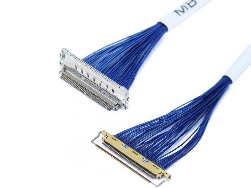
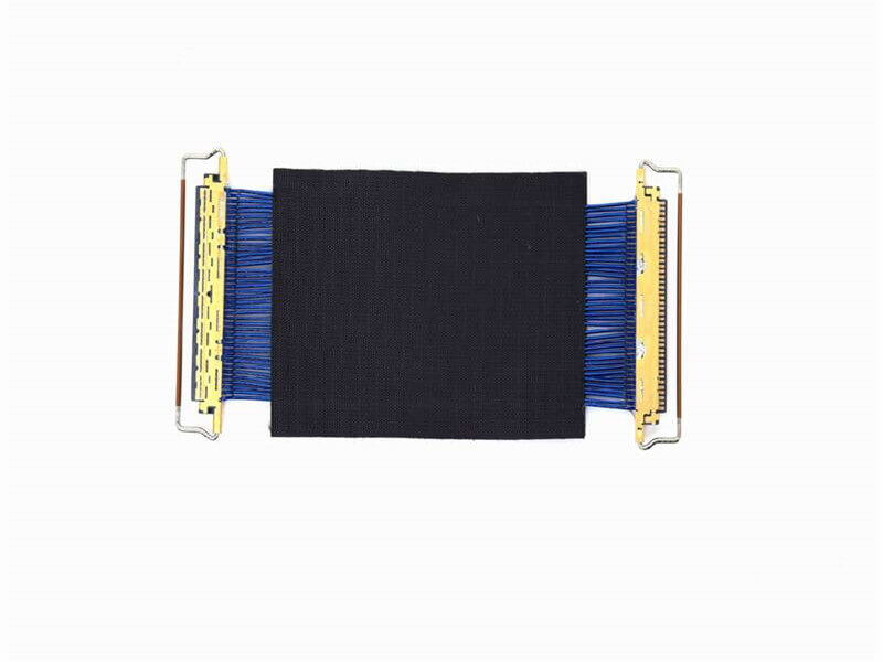
Best

Micro Coaxial Cable factory

Mitigating Signal Interference in Micro-Coaxial Cables

Abstract‌
Signal interference remains a critical challenge in high-frequency applications using micro-coaxial cables, impacting performance in 5G devices, medical imaging systems, and aerospace electronics.

  1. Introduction
    Micro-coaxial cables are ubiquitous in modern electronics, yet their compact size and high operating frequencies (up to 110 GHz) make them vulnerable to signal interference. Even minor disruptions can degrade data integrity in applications like autonomous vehicle LiDAR or 6G mmWave communications. This article outlines systematic approaches to minimize interference through design, testing, and material innovation.
  2. Sources of Signal Interference
    2.1 Electromagnetic Interference (EMI)
    ‌External Sources‌: Nearby RF transmitters, power lines, or switching circuits induce noise.
    ‌Internal Sources‌: Signal leakage due to inadequate shielding.
    2.2 Crosstalk
    ‌Capacitive Coupling‌: Adjacent cables in multi-channel systems (e.g., smartphone camera arrays) capacitively transfer noise.
    ‌Inductive Coupling‌: Current loops in high-speed data lines generate magnetic interference.
    2.3 Impedance Mismatches
    ‌Connector Discontinuities‌: Poorly matched connectors reflect signals, causing standing waves.
    ‌Bend-Induced Variations‌: Flexing alters cable geometry, leading to impedance fluctuations.
  3. Shielding Design for EMI Suppression
    3.1 Multi-Layer Shielding Architectures
    ‌Tri-Shield Designs‌:
    ‌Layer 1‌: Braided copper (85–95% coverage) for flexibility.
    ‌Layer 2‌: Conductive polymer film (e.g., carbon-loaded PEEK) for high-frequency EMI absorption.
    ‌Layer 3‌: Aluminum foil with 100% coverage for static shielding.
    ‌Performance‌: Reduces EMI by 40–60 dB in 10–40 GHz range (tested per IEC 62153-4-7).
    3.2 Grounding Techniques
    ‌360-Degree Connector Grounding‌: Ensures low-impedance paths to chassis ground, minimizing ground loops.
    ‌Distributed Ground Stitching‌: Multiple ground vias in PCB connectors suppress resonance.
    3.3 Case Study: Automotive Radar Cables
    ‌Challenge‌: 77 GHz radar cables in self-driving cars faced EMI from onboard inverters.
    ‌Solution‌: Double-shielded cables with ferrite-loaded jackets reduced noise by 35 dB.
  4. Crosstalk Mitigation Strategies
    4.1 Physical Separation and Routing
    ‌Twisted Pair Configuration‌: Crosstalk reduced by 20 dB when spacing exceeds 3× cable diameter.
    ‌Orthogonal Routing‌: Crossing adjacent cables at 90° minimizes inductive coupling.
    4.2 Dielectric Isolation
    ‌Foam vs. Solid Dielectrics‌: Foamed PTFE (ε_r = 1.3) lowers capacitive coupling by 30% compared to solid PTFE (ε_r = 2.1).
    4.3 Differential Signaling
    ‌LVDS and C-PHY Protocols‌: Cancel common-mode noise through differential pairs.
  5. Impedance Control and Termination
    5.1 Precision Manufacturing
    ‌Tolerance Management‌: Maintaining ±0.02 mm conductor diameter ensures 50/75 Ω impedance stability.
    ‌Laser-Trimming‌: Adjusts connector pads to match cable impedance (tested via TDR).
    5.2 Bend-Resistant Designs
    ‌Corrugated Shields‌: Preserve geometry during flexing (e.g., foldable smartphones).
    ‌Strain-Relief Boots‌: Limit bend radius to >5× cable diameter.
    5.3 Connector Optimization
    ‌SMA vs. SMPM Connectors‌: SMPM interfaces offer better impedance matching up to 65 GHz.
  6. Material Innovations
    6.1 Advanced Shielding Materials
    ‌Graphene-Coated Shields‌: Achieve 100 dB shielding effectiveness (SE) at 0.1 mm thickness.
    ‌Metamaterial Cladding‌: Frequency-selective surfaces block specific EMI bands.
    6.2 Low-Loss Dielectrics
    ‌Porous Silica Composites‌: Reduce dielectric loss to 0.0001 at 60 GHz.
  7. Testing and Validation
    7.1 EMI Testing
    ‌Radiated Emissions‌: ANSI C63.4-compliant anechoic chamber tests up to 40 GHz.
    ‌Conducted Susceptibility‌: Inject noise via current probes to measure immunity.
    7.2 Time-Domain Reflectometry (TDR)
    ‌Impedance Profiling‌: Detect discontinuities with <1 ps time resolution.
    7.3 Eye Diagram Analysis
    ‌High-Speed Links‌: Validate signal integrity for PCIe 6.0 (64 GT/s) or USB4.
  8. Case Study: 5G Base Station Cables
    ‌Interference Issue‌: Crosstalk between 28 GHz antenna feeds caused beamforming errors.
    ‌Solution‌:
    Quad-shielded micro-coaxial cables with air-spaced dielectrics.
    Impedance-matched field-replaceable connectors.
    ‌Outcome‌: EVM (Error Vector Magnitude) improved from 8% to 2.5%.
  9. Future Trends
    ‌AI-Driven EMI Prediction‌: Machine learning models optimize shield layering.
    ‌3D-Printed Cables‌: Gradient-density dielectrics for frequency-adaptive performance.

More Micro Coaxial Cable related Products

Micro Coaxial Cable
Micro Coaxial Cable

Micro Coaxial Cable: High-Quality Solutions for Precision Applications Micro coaxial cables are essential components in high-performance electronic applications, providing reliable signal transmission in compact and flexible designs. A.

More information
KEL Micro Coaxial Cable

KEL’s Micro Coaxial Cable solutions are at the forefront of modern electronic connectivity, offering exceptional performance in high-speed data transmission, miniaturization, and reliability. These connectors are integral to various.

More information
I-PEX Micro Coaxial Cable

Overview of I-PEX Micro Coaxial Cable Connectors I-PEX is a global leader in micro coaxial cable solutions, specializing in high-performance IPEX micro coax connectors and micro coaxial cable assemblies. These products are designed for.

More information
LVDS Micro Coaxial Cable

In LVDS (Low Voltage Differential Signaling) display systems, Micro-coaxial Cable (also referred to as Micro Coax Cable) stands out as an optimal solution for high-resolution, high-reliability signal transmission. Designed to meet the str.

More information
Micro Coaxial Cable Service