RF Micro Coaxial Cable
Meta Description: Discover premium RF micro coaxial cables engineered for high-frequency signal transmission in compact devices. Explore specs, applications, and benefits for telecom, medical, and aerospace industries. .
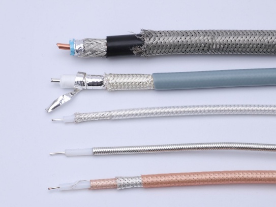
Coaxial cables have been a cornerstone of wired communication systems for decades, prized for their ability to transmit high-frequency signals with minimal interference. From broadcasting and telecommunications to military and aerospace applications, their unique design ensures reliable performance in demanding environments.
Central Conductor: A solid or stranded copper core (or aluminum alloy) carries the electrical signal.
Dielectric Insulator: Surrounds the conductor, maintaining a fixed distance between the core and shield. Common materials include polyethylene foam (low loss) or PTFE (high-temperature stability).
Metallic Shield: Braided copper, aluminum foil, or a combination of both. This layer blocks external electromagnetic interference (EMI) and confines the signal within the cable.
Outer Jacket: Protects against physical damage and environmental factors (e.g., UV-resistant PVC or flame-retardant materials).
This design creates a self-shielding transmission line, minimizing signal leakage and external noise ingress.
2. Key Transmission Characteristics
A. Frequency Bandwidth and Attenuation
Bandwidth:
Standard coaxial cables support frequencies from 5 MHz to 18 GHz, depending on the type.
75Ω cables (e.g., RG-6): Optimized for video and broadband signals (up to 3 GHz).
50Ω cables (e.g., LMR-400): Used in RF and microwave systems (up to 6 GHz).
Attenuation (Loss):
Expressed in dB per meter (dB/m), attenuation increases with frequency. For example:
RG-58 (50Ω): ~0.24 dB/m at 100 MHz, ~0.63 dB/m at 1 GHz.
Low-loss Heliax (1-5/8″): ~0.03 dB/m at 3 GHz.
Losses arise from conductor resistance, dielectric absorption, and skin effect.
B. Characteristic Impedance
Impedance Matching:
Coaxial cables are designed with standardized impedances (e.g., 50Ω, 75Ω) to match source and load impedances.
Mismatched impedance causes signal reflections (VSWR >1), leading to power loss and distortion.
Impedance Stability:
Variations in dielectric uniformity or shield integrity (e.g., bending) can alter impedance, degrading signal quality.
C. Shielding Effectiveness
EMI/RFI Rejection:
Braided shields provide ~60–90 dB attenuation against external interference.
Quad-shield cables (foil + dual braid) exceed 100 dB shielding for critical applications (e.g., satellite communications).
Signal Leakage:
Poor shielding allows signal radiation, which can interfere with nearby systems or violate regulatory standards (e.g., FCC Part 76 for cable TV).
D. Power Handling Capacity
Determined by conductor size and dielectric strength:
Average Power: Limited by thermal dissipation. For example, RG-213 handles ~2.8 kW at 3 MHz.
Peak Power: Limited by voltage breakdown. PTFE-insulated cables tolerate >10 kV in pulsed systems.
3. Environmental and Operational Factors
A. Temperature Stability
Dielectric Materials:
PTFE: Operates from -65°C to +260°C (ideal for aerospace).
Polyethylene: Limited to -40°C to +80°C.
Phase Stability:
Temperature fluctuations cause minor changes in cable length and impedance, critical in phased-array radar systems.
B. Flexibility and Durability
Stranded Conductors: Improve flexibility for routing in tight spaces (e.g., RG-174).
Corrosion Resistance:
Silver-plated shields enhance longevity in humid or salty environments (e.g., marine systems).
C. Bend Radius
Minimum bend radius (~10× cable diameter) prevents kinking and shield deformation.
4. Comparative Performance with Other Cables
Characteristic Coaxial Cable Twisted Pair Fiber Optic
Bandwidth Up to 18 GHz Up to 1 GHz (Cat 8) 10+ THz
Max Distance 500m (with amplifiers) 100m (Ethernet) 100+ km
EMI Immunity Excellent Poor (unshielded) Immune
Cost Moderate Low High
5. Applications Based on Transmission Properties
A. High-Frequency Signal Transmission
Satellite Communications: Low-loss coaxial cables (e.g., LMR-600) connect antennas to modems.
Cellular Base Stations: Heliax cables link RF transceivers to antennas.
B. Video and Broadband Distribution
CATV Networks: 75Ω RG-6 cables deliver HD/4K signals to homes.
Surveillance Systems: Siamese coaxial cables (combined power and video) for CCTV cameras.
C. Military and Aerospace
Avionics: Lightweight, fire-resistant coaxial cables (MIL-DTL-17) for cockpit instrumentation.
Radar Systems: Phase-stable cables ensure precise signal timing.
6. Selection Guidelines
Frequency Range: Choose low-loss cables (e.g., foam dielectric) for >1 GHz applications.
Shielding: Opt for quad-shielded cables in high-EMI environments.
Impedance: Match 50Ω for RF systems, 75Ω for video.
Environmental Needs: Use PTFE jackets for extreme temperatures or corrosive settings.
7. Future Developments
Ultra-Low-Loss Cables: Incorporating air dielectric or advanced polymers for 5G mmWave networks.
Smart Cables: Embedded sensors to monitor real-time attenuation and impedance.
Meta Description: Discover premium RF micro coaxial cables engineered for high-frequency signal transmission in compact devices. Explore specs, applications, and benefits for telecom, medical, and aerospace industries. .
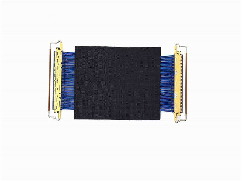
Micro Coaxial Cable: High-Quality Solutions for Precision Applications Micro coaxial cables are essential components in high-performance electronic applications, providing reliable signal transmission in compact and flexible designs. A.

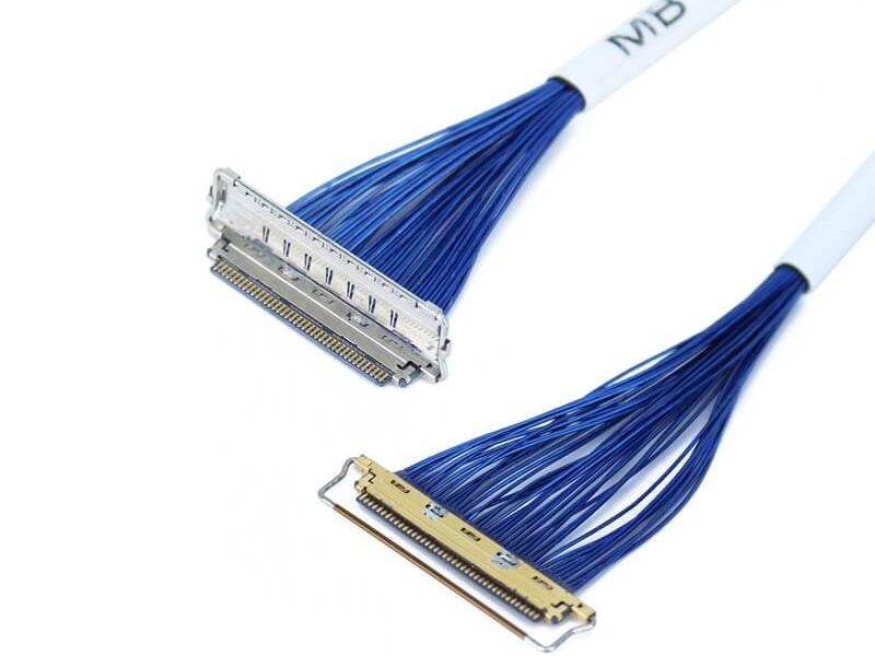
KEL’s Micro Coaxial Cable solutions are at the forefront of modern electronic connectivity, offering exceptional performance in high-speed data transmission, miniaturization, and reliability. These connectors are integral to various.

Overview of I-PEX Micro Coaxial Cable Connectors I-PEX is a global leader in micro coaxial cable solutions, specializing in high-performance IPEX micro coax connectors and micro coaxial cable assemblies. These products are designed for.
In LVDS (Low Voltage Differential Signaling) display systems, Micro-coaxial Cable (also referred to as Micro Coax Cable) stands out as an optimal solution for high-resolution, high-reliability signal transmission. Designed to meet the str.