RF Micro Coaxial Cable
Meta Description: Discover premium RF micro coaxial cables engineered for high-frequency signal transmission in compact devices. Explore specs, applications, and benefits for telecom, medical, and aerospace industries. .
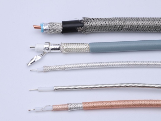
Conductor Design: Solid or stranded copper cores (often silver-plated) reduce skin effect losses at high frequencies.
Dielectric Material: Low-loss insulators like PTFE (εr ≈ 2.1) or foamed polyethylene minimize signal attenuation.
For example, ultra-miniature cables (0.3 mm diameter) used in 5G mmWave applications maintain a bandwidth of 50 GHz with insertion loss below 0.5 dB/cm at 30 GHz.
1.2 Attenuation and Loss Characteristics
Signal attenuation in micro-coaxial cables arises from:
Conductor Resistance: Governed by the skin depth effect, especially above 1 GHz.
Dielectric Loss: Energy absorbed by the insulating material, quantified by its loss tangent (tan δ).
Radiation Loss: Minimal due to robust shielding.
High-performance cables achieve attenuation as low as 0.1 dB/m at 1 GHz, critical for long-distance data links in aerospace or medical imaging.
1.3 Impedance Stability
A consistent characteristic impedance (typically 50 Ω or 75 Ω) ensures minimal signal reflections. Variations in impedance (<±2 Ω) are controlled through:
Precision Manufacturing: Uniform conductor diameter and dielectric thickness.
Shielding Integrity: Tightly woven braided shields or dual-layer foil designs prevent impedance fluctuations caused by external EMI.
2. Factors Influencing Transmission Performance
2.1 Material Selection
Conductor: High-purity oxygen-free copper (OFC) or silver-plated copper enhances conductivity.
Dielectric: PTFE offers low tan δ (0.0003 at 10 GHz), while polyethylene balances cost and performance.
Shield: Multi-layer shields (e.g., aluminum foil + tinned copper braid) achieve >90 dB EMI suppression.
2.2 Environmental Conditions
Temperature: PTFE-insulated cables operate stably from -65°C to +200°C, avoiding dielectric degradation.
Flexibility: Dynamic applications (e.g., robotic arms) require cables with bend radii <5× diameter and >100,000 flex cycles.
Moisture and Chemicals: Fluoropolymer jackets resist hydrolysis and corrosive fluids, maintaining performance in harsh environments.
2.3 Connector and Termination Quality
Poorly terminated connectors introduce impedance mismatches and VSWR (Voltage Standing Wave Ratio) >1.5, degrading signal quality. Laser-welded or crimped connectors ensure:
Low Contact Resistance: <10 mΩ. High Return Loss: >20 dB at 20 GHz.
3. Performance Optimization Techniques
3.1 Advanced Shielding Designs
Tri-Shield Technology: Combines foil, braid, and drain wire for >100 dB EMI/RFI isolation.
Semi-Rigid Construction: Solid outer shields in aerospace-grade cables eliminate flex-induced signal loss.
3.2 Low-Loss Dielectric Innovations
Air-Spaced Insulation: Reduces dielectric constant (εr ≈ 1.0) for ultra-high-frequency applications.
Nano-Ceramic Coatings: Applied to conductors to suppress surface oxidation and minimize resistance.
3.3 Signal Equalization and Compensation
Pre-Emphasis: Boosts high-frequency signals in long cables to counteract attenuation.
DSP-Based Correction: Used in medical endoscopes to restore distorted video signals.
4. Application-Specific Performance Benchmarks
4.1 High-Speed Data Transmission
6G Research: Micro-coaxial cables with 67 GHz bandwidth enable terahertz signal testing.
HD Endoscopy: 4K video transmission at 12 Gbps with BER (Bit Error Rate) <10-12.
4.2 RF and Microwave Systems
Radar Arrays: Phase-stable cables with ±0.5° phase matching over 18–40 GHz.
Satellite Communications: Group delay variation <1 ps/m up to 30 GHz.
4.3 Medical Diagnostics
MRI Coils: Cables with <0.1 dB loss at 3 Tesla (128 MHz) ensure high SNR (Signal-to-Noise Ratio).
Intravascular Ultrasound: 40 MHz signals transmitted over 2-meter cables with <3 dB total loss.
5. Future Trends and Challenges
5.1 Emerging Technologies
Photonic-Coaxial Hybrids: Integrating optical fibers with micro-coaxial cables for ultra-wideband systems.
Graphene Conductors: Theoretical attenuation reduction by 50% compared to copper.
5.2 Sustainability Demands
Recyclable Materials: Bio-based dielectrics and lead-free shielding to meet RoHS/REACH standards.
5.3 Miniaturization Limits
Pushing outer diameters below 0.1 mm without compromising shielding remains a key challenge.
Meta Description: Discover premium RF micro coaxial cables engineered for high-frequency signal transmission in compact devices. Explore specs, applications, and benefits for telecom, medical, and aerospace industries. .
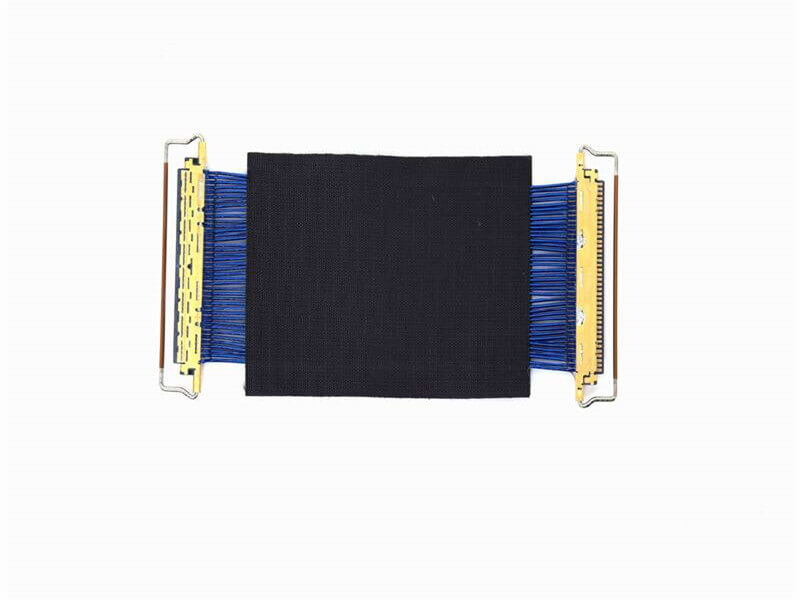
Micro Coaxial Cable: High-Quality Solutions for Precision Applications Micro coaxial cables are essential components in high-performance electronic applications, providing reliable signal transmission in compact and flexible designs. A.

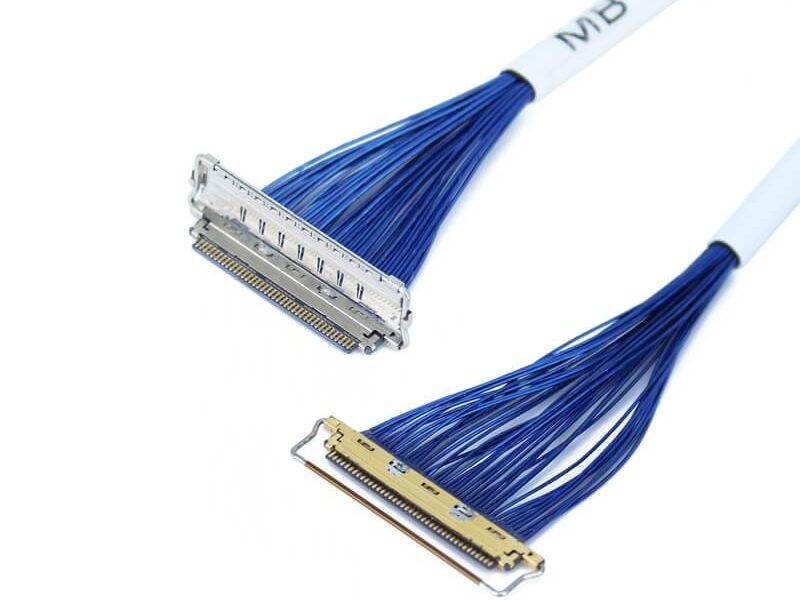
KEL’s Micro Coaxial Cable solutions are at the forefront of modern electronic connectivity, offering exceptional performance in high-speed data transmission, miniaturization, and reliability. These connectors are integral to various.

Overview of I-PEX Micro Coaxial Cable Connectors I-PEX is a global leader in micro coaxial cable solutions, specializing in high-performance IPEX micro coax connectors and micro coaxial cable assemblies. These products are designed for.
In LVDS (Low Voltage Differential Signaling) display systems, Micro-coaxial Cable (also referred to as Micro Coax Cable) stands out as an optimal solution for high-resolution, high-reliability signal transmission. Designed to meet the str.